Friday, 28 September 2012

Chassis Schematic

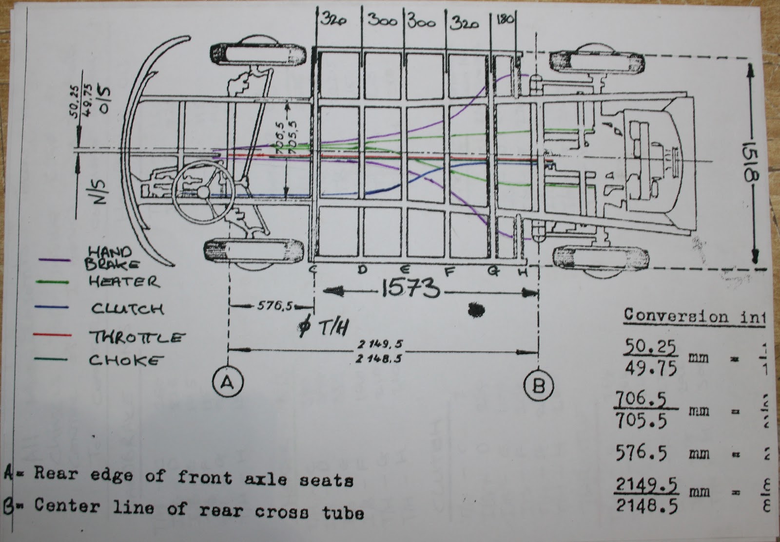
Long before the body was finished, we took very detailed measurements of the chassis and conduit runs and have produced a diagram with all these details on it.

We are happy for anyone to make use of this diagram in their restoration, but please acknowledge us as the source. We know that these details are 100% correct for our 1952 van, but the conduit routes did change from year-to-year.


Thursday, 27 September 2012

The Lower Engine Block Virtually Done

We've continued to assemble the engine, fitting up more NOS parts and the lower engine block is now virtually finished:

Below we are using feeler gauges to set the tappets:


Here the cylinder head tinware is now fitted over the top of the cylidners. Note: early engines include a piece that fits between the barrel & piston and the block, so you need it in place first.

Here you can see the covers from the top:

Rocker covers, rocker cover gaskets and clips now fitted up as the valve adjustments are all done.


We can turn the engine upside down on our engine stand so we can fit up the sump plate and sump gaskets:


The early pre '60 heater boxes are treated to some heat-resistant paint, then gloss black, then lacquered.
These will be fitted upto the engine very soon. 

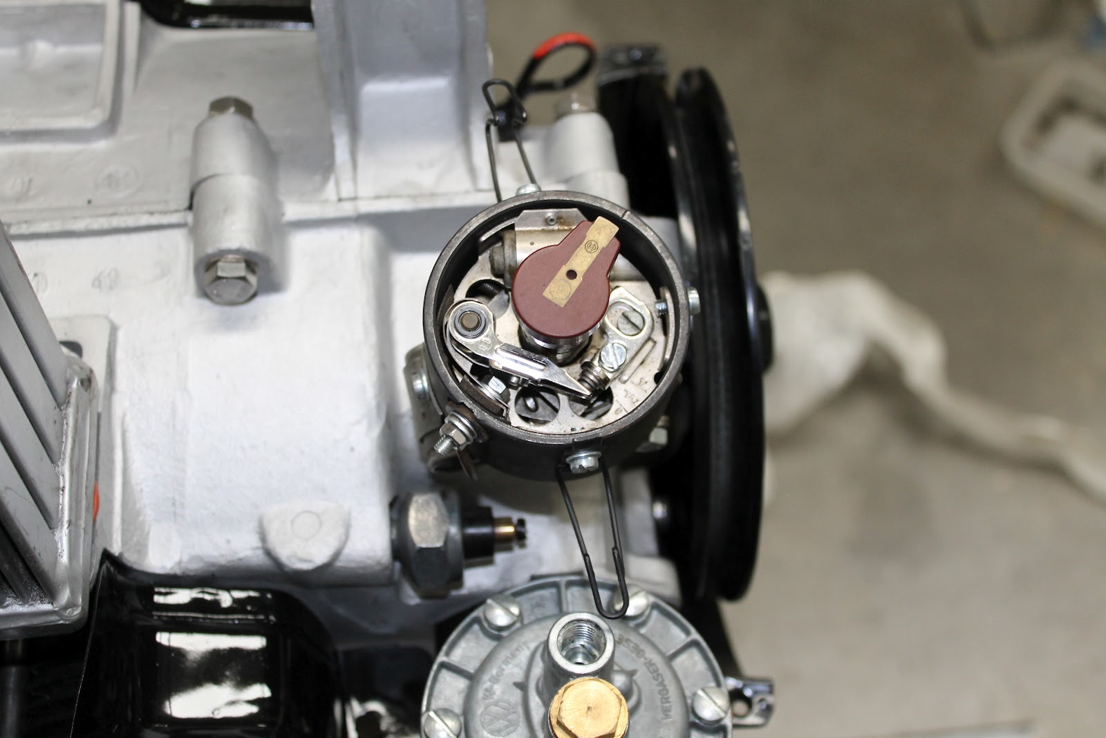
Next we fit up the correct pre '53 Distributor. The early engines had a flat topped distributor with the wires coming out of the side. The NOS is perfect and complete with original BOSCH plate.

The view from the top showing the rotor arm and points in place. 

The correct early style flat cap is now fitted.

The basic lower block of the engine is now finished. Next we will fit the heater boxes, the exhaust and then work on the upper engine such as the manifold, carburettor, the fan and thermostat and fan shroud.

We will also attach a spare gearbox with the starter motor and very soon fire it up back into life. We'll video the start up and post it on the blog for you all to see!!

Monday, 17 September 2012

Engine Build Continues....

Work continues assembling the engine. 

You can see below that this side of the case is now finished. The con-rods are sticking out ready for the pistons / barrels to be attached.


Below you can see the correct 25hp oil pump fitted. You can use any pre 1967 oil pump on these engines, but the correct one has a thinner plate as the edges / sides are more curvy

Now you can see below the correct domed-top oil cooler and the barrels fitted
You can again use a standard single-port oil cooler, but we had a few original 25hp domed top ones lying about so we used the correct one. Again with barrels & pistons, we can sometimes supply sets of 25hp ones, but readily available are 30hp ones.

Engine studs are all now in place ready to accept the cylinder heads.

Work now starts on lapping in the engine valves. Note here the difference between these two exhaust valves. The one on the left has a cut-in mark around it. We can supply valves for all years and sizes of engine.

Here we are setting the end float, we carefully measure this as its essential to set this correctly.  We offer a handy little tool for doing this yourself. Click here.

The crankshaft main oil seal is now fitted

Next the flywheel and gland nut go on

The fuel pump is now in place and the dip stick fitted with the blob of red paint to high-light a service point. 


Wednesday, 29 August 2012

Fitting Out the Crank Case

After the rotating assembly was fully weighed and balanced, we can now assemble it and trial fit it into the crankcase.

Here the rotating crank shaft assembly is fitted into the case

Next the cam-shaft is fitted into place

Here you can see the timing marks on the cam wheel lining up with the mark on the cam drive gear:

Here you should be able to see the difference between the con-rods showing just how much work has gone into taking material off each one so they balance perfectly:

Rocker Assemblies

We've re-built the complete rocker-assemblies using a combination of NOS rocker shafts and the original parts. Everything now moves freely and is ready for assembly in the engine.


The NOS rocker shafts before assembly:

We can supply NOS rocker shafts suitable for 25hp and 30hp engines - click here to buy yours

Engine Assembly

Now we get to the exciting point of assembling the engine. But before we did, we thought it would be fun to lay out all the parts in a kind of exploded view:


So there are all the bits of the engine. All we need to do now is bolt it altogether!!!!

Engine Balancing


Whilst the engine is stripped down to the very last nut and bolt, we took the opportunity to have the whole rotating assembly balanced

Basically each single part is weighed and then is ground down to remove material so it is perfectly balanced in the rotating plane.

Whilst we accept this is not something VW did, it certainly will improve the life of the engine, its longevity and is smoother running:


You can see on the NOS crank shaft below where some material has been taken out of the crank. This is to ensure its perfectly balanced and rotates evenly too:

Here you can see the amount of material removed from the top of one of the con-rods. These were NOS con-rods but the weight difference between the 4 rods was staggering. 
">
You can see here that some material as also been removed from the bottom of the con-rod


On the pistons, material is removed from the inside edge of the piston itself. Again, these were NOS pistons, but they are now all exactly the same weight. Down to the nearest micron.


When it comes to balancing the flywheel and clutch, they are put together so they rotate equally together. You can see in the bottom left corner of the flywheel a small amount has been removed to perfectly balance it. There's also small paint dab just to the left of the top dowel mount in the middle - this lines up with a dab on the clutch disc - this is how they must be fitted so they rotate perfectly together.


Some material has also been removed from the clutch disc again so its perfectly balanced.